The installation of a new Lowrance HDS LIVE system can easily be achieved by the average boat owner and you really don’t need to be a certified electrician to complete the task safely. Of course if you’re not at all confident with this sort of stuff then it goes without saying that you should leave it to the professionals. But for those keen on having a crack to save a few bucks and achieve some self-satisfaction through a bit of home DIY, this is a basic run down of how I went about it on our fibreglass hull.
Removal Time
Despite initially appearing to be a fairly quick and easy job the removal of the old sounder system actually proved to be the most labour-intensive part of the whole changeover process. It’s amazing how the various mod-cons and accumulation of extra wires over the years can actually cause a headache or two down the track when no real long term planning has gone into the decisions at the time. And after this experience I’ll certainly be putting a lot more thought into any future add-ons!
Careful planning was taken to ensure correct mounting of the head unit bracket
The benefit of modern day Lowrance systems at least is that a lot of the extra wires and cables are done away with and the units are far more capable with less external bits ‘n’ pieces so to speak. I no longer required the old StructureScan module which is now technically inbuilt within the HDS LIVE and this also freed up the ethernet network capability of the sounder for future additions. The Active Imaging transducer replaced the need to have two separate sonar transducers thanks to its 3 in 1 capability whilst the pre-existing NMEA 2000 backbone was left in place for any accessory add-ons.
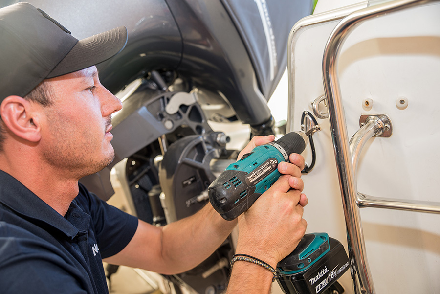
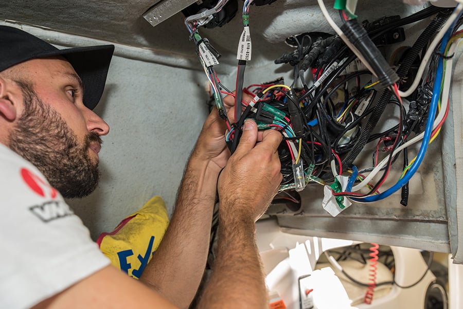
The whole process easily falls within the average boat owner’s skillset
We also made the decision to remove our old Lowrance SonicHub sound system with a plan to eventually replace it with a JL audio system. With less wiring to contend with it signalled a great opportunity to re-route a few existing cables and tidy up in areas behind the dash to make it look somewhat more respectable compared to the birds nest that greeted us initially. It’s also worth clarifying that the battery isolator was turned off through this whole process to ensure there was no risk of serious electrical harm or injury. So with the boat looking a few kilo’s lighter it was then off for some fibreglass repair work to patch-up a few of the holes left behind that were no longer required for installation of the new setup.
Head Unit Mounting
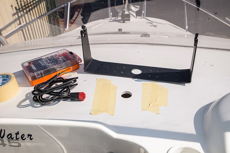
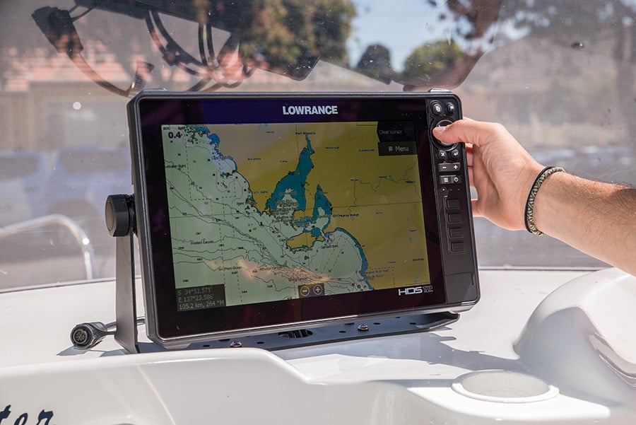
With a quick makeover and the boat returned to its rightful owner the mounting of the head unit was first up. Our dash isn’t configured for a flush mount head unit so careful consideration was instead made to where the external mounting bracket should be installed.
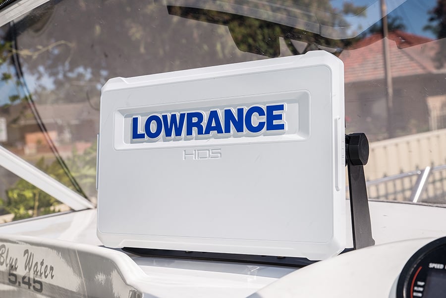
The head unit install completed. What an awesome looking piece of kit!
I was initially apprehensive jumping up to a 12-inch screen from our previous 10-inch version with limited room available, so we had to ensure this process was very accurate. I certainly wasn’t keen on the idea of further fibreglass repairs either given the expensive nature of the work. After careful consideration and comparing the size dimensions of old vs new in this instance however it turned out that the HDS LIVE 12 wasn’t actually too dissimilar to our old Lowrance Gen2 HDS 10. In fact, it was almost a like for like size replacement apart from a centimetre or two given the slimline design of the LIVE and a much narrower key panel thanks to the touch screen capability of these units. It still amazes me that somehow they’ve been able to fit even better tech into a smaller shell and as a result this meant I could jump up to a bigger screen without compromising dash room. This will undoubtedly help with our fishing exploits to come.
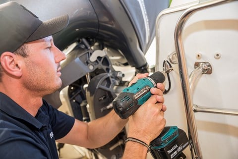
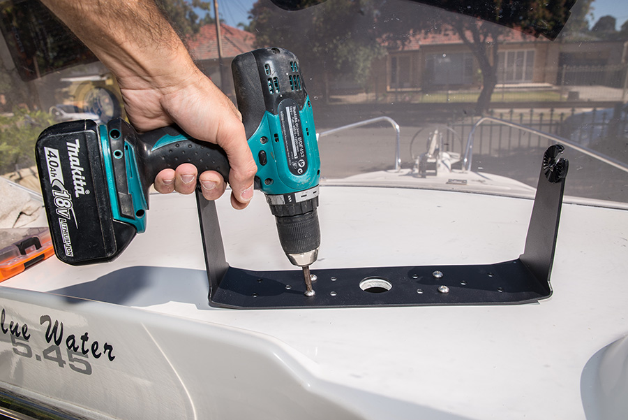
With the head unit dummied up the mounting bracket holes were then marked out by using the bracket as a template. This was cross-checked with the underside of the dash and thankfully there were no obstacles or hidden surprises in the way. The battery isolator was once again powered off for obvious safety reasons.
I then proceeded to drill the mounting bracket pilot holes and used a hole saw for a larger centre cut out where the wires could run up through from beneath the dash. A little tip here for glass boat owners is to cover the gelcoat with masking tape as this can help reduce the amount of fracturing that can occur around the hole. Be patient and slowly work your way up in drill size for the mounting holes until you reach the desired diameter and you should be sweet. As for the hole saw try running the drill in reverse initially to create an imprint and then gently work your way through without too much pressure or force. Once the holes were finished it was then a matter of mounting the bracket with the provided nuts and bolts.
Wiring Up
Onto the wiring configuration and this will undoubtedly vary between behind-dash electronic setups but with easily accessibly positive and negative accessory terminals on my boat the process was seriously straight forward. An in-line fuse that is provided separately in the box had to be connected to the positive wire from the HDS power cable and I chose to use what I would call a bullet point crimp otherwise you may very well wish to solder the join and heat shrink it.
A quick power up was performed to ensure everything was wired up correctly
An eyelet ring terminal was then crimped onto the other end of the fuse wire and another was also placed on the negative wire of the power cable before joining them both onto the appropriate accessory power terminals (once again flagging that the battery isolator remained off at this point). The remaining yellow wire was not required as this is an accessory wake up designed to control the power state of external equipment. Once I was happy a quick power up was performed to confirm that things were in working order and thankfully after a short breath hold the unit came aLIVE. It was that simple!
Transducer Attention to Detail
We naturally left the installation of the transducer until very last as this requires extra time and thought to plan out correctly. Transducer placement is critical for a crisp detailed sounder return and if you get it wrong then you certainly won’t see the results on screen that you would expect with such an awesome kit of Lowrance sonar. Most setups will require the transom bracket that comes with the transducer to mount it effectively. Where this sits is largely dependent on your hull design, transom configuration and available room.
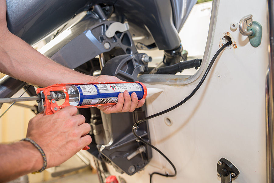
Below waterline marine sealant is required to seal off your transom screw holes
More complex designs and setups may need to consult the manual further for more ideas on mounting options and locations whilst some boats also have purpose designed areas to avoid drilling into the hull. Our transom was quite bare bones in nature but with a previously mounted LSS StructureScan transducer that gave us quite clear readings it was a pretty easy changeover process to place it roughly in the same location. What made this location the best spot for our hull is that the transducer remains in the water when the boat is on the plane thus providing a constant bottom depth reading even at high speeds. This is critical if the Active Imaging 3-in-1 is your only transducer mounted to the boat.
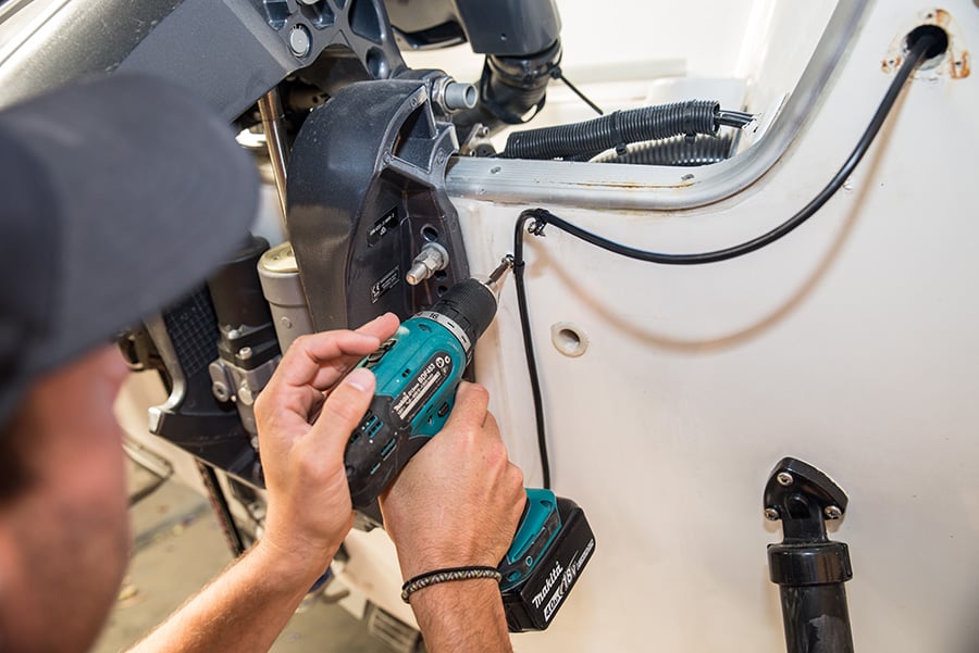
Putting the finishing touches on the transducer cable transom mounting process
The mounting spot is also away from any lifting strakes on the underside of the hull which tend to provide turbulence that impairs the flow of clean water over the face of the transducer resulting in a poor image return. These are some of the characteristics that you’re looking for in an ideal mounting location for your 3-in-1 Active Imaging transducer and once you’ve located the best spot it’s onto the mounting process.
Keep in mind that the boat may not be sitting perfectly horizontal on the trailer so use a few transom reference points to mark up some levels with a pencil in the likely mounting location. The transducer should ideally sit right on the bottom edge of the transom slightly lower than the hull but not too low that it will cause excess drag through the water. It can’t sit too high either because the transducer won’t experience a clean flow of water over its face.
A stainless vent-hole cover provided a neat finish when running the transducer cable into the boat
As long as you’re in the ballpark however the transducer can still be adjusted vertically when being fixed onto the hull as the grill plate style of mounting bracket allows for fine tuning this process. The bracket was outlined with a pencil and the screw holes were also marked out and drilled accordingly before being filled with some marine grade below waterline sealant. The bracket was held in place over the template we had marked out and the screws were mounted most of the way in with some final adjustments made to ensure it sat level on both the vertical and horizontal axes before tightening the screws completely.
With the transducer mounted all that was left to do was run the cable along the transom in a neat configuration. This was achieved with cable clips screwed into pre-drilled holes with plenty of marine sealant to block them off. The cable entered the boat through the transom wall via a hole saw cut out just wide enough to push the 9-pin connecter head through before being sealed up with some more sealant and a stainless-steel vent hole cover to provide a neat finish. We ran the cable under the gunnels to the helm and zip tied it to existing wires along the way to ensure it was tucked up and out of sight. The 9-pin connector was pulled through the head unit mounting bracket to join the existing power and NMEA cables and this final piece of the puzzle signalled that the job was done.
A bit of dash re-wiring was well overdue
Upon reflection things were pretty smooth sailing and provided you are well prepared with all the tools and equipment you’ll need then it easily falls within the skillset of the (very) average handy boat owner. Don’t forget to consult your HDS LIVE installation guide for a more detailed reference or ideas on how you could adapt the install for your particular setup. It’s not overly complicated stuff and it truly is satisfying to sit back and admire your own handy work with one of the best available sounders on the market now and up running at your fingertips.


